Geometry and Plot Plan
Everything Kryptos calculates is measured against your 3D plant model, so importing the geometry and aligning the plot plan with it is the first step after creating a new project.
Import Geometry
The Geometry ribbon runs along the top of the Geometry tab. Import Geometry is the first button on the ribbon.
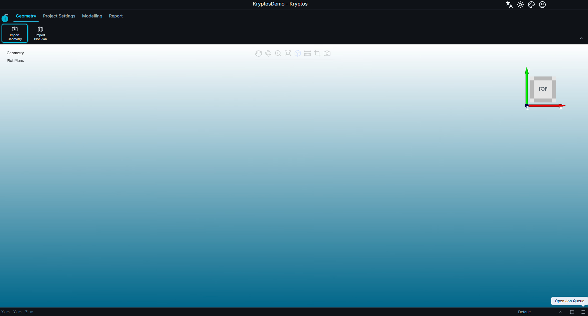
- Import Geometry — opens a file picker followed by the import settings dialog.
Supported Formats
You can import Navisworks files (.nwd and .nwc) directly into Kryptos. It reads these files and also keeps the model's parts, so you can split the model by category (equipment, piping, structure, etc.) while importing.
| Format | File type |
|---|---|
| Navisworks | .nwd, .nwc |
| Kryptos Geometry | .kryptosgeo |
| Kryptos Catalogue | .kryptcat |
| 3D mesh files | .stl, .obj, .ply |
Any other CAD file (example RVM, PDMS, DGN etc) that can be opened in Navisworks can be saved as an .nwd file first, and then imported. This way you can import almost all geometry formats available.
You can select multiple files at once. The import settings you choose will apply to all files in the selection. If different files require different placement or settings, import them separately.
TIP
Choose a Kryptos Catalogue (.kryptcat) file on its own. It cannot be imported together with other files, and it asks for a name, tag, colour and triangle reduction for each of its folders. For more details on Kryptos Catalogue file refer Navisworks Exporter Plugin.
Import Settings
The Import Geometry Settings dialog has two tabs. General Settings holds what every import needs. Advanced Settings holds settings that most imports leave as they are. If a value on the Advanced Settings tab is not valid when you click OK, Kryptos opens that tab so you can fix it.
General Settings
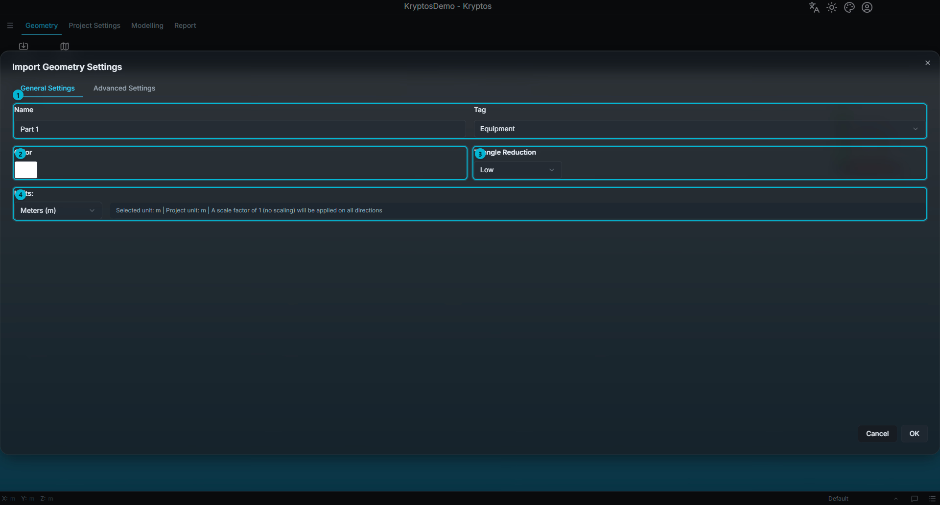
- Name and Tag
- Color
- Triangle Reduction
- Units
Geometry Name
Name determines how the imported geometry appears in the geometry tree. It must contain at least two characters. New imports are named Part 1 until you change it.
TIP
If you select multiple files at once, the name you enter is used as the name stem, and each file becomes a separate entry. For example, entering PlantModel creates entries such as PlantModel_part1, PlantModel_part2, and so on, in the order in which the files were selected.
Units
Units describes the units used by the incoming file; it is not a project preference. Select the unit in which the file was modelled: metres, feet, inches, or millimetres. Selecting the correct unit is essential for importing the model at the correct scale.
Kryptos compares the selected unit with the project unit and displays the resulting conversion in the grey note beside the dropdown:
Selected unit: ft | Project unit: m | A scale factor of 0.3048 will be applied on all directions
Check this message before continuing. If it shows 1 (no scaling) when you expected a unit conversion, or shows a conversion when you expected none, verify the Units setting.
TIP
If your model is not in metres and you want the whole project to use that unit instead, set the project unit in Project Settings first, before you import. Changing the project unit after geometry is already imported does not resize it — you would need to re-import the geometry.
Tag
Tag classifies the imported geometry as Equipment, Piping, Structure, Electrical, Safety, HVAC, or Miscellaneous.
Consistent tagging makes large plant models easier to navigate and manage, so it is recommended to assign the appropriate tag during import rather than correcting it later.
WARNING
Geometry tagged Miscellaneous is not considered in calculations. Use it only for items that should be visible but should not affect the results.
Color
Pick Color sets the colour used to display the geometry in the 3D viewport.
Colour-coding geometry by discipline—for example, using one colour for piping and another for structural elements—can make a dense plant model significantly easier to interpret.
When you import a Navisworks file, the colour setting becomes a dropdown with two choices:
- Use Navisworks Colours — every part keeps the colour it has in Navisworks. This is the default.
- Custom — every part is shown in the single colour you pick.
Triangle Reduction
Plant models can contain very large numbers of triangles, particularly at advanced stages of development. Triangle Reduction simplifies the mesh during import by reducing the number of triangles while preserving the overall geometry and shape of the model. This can improve 3D viewport performance, particularly when working with large and highly detailed plant models.
| Setting | Effect on the Model | Use When |
|---|---|---|
| None | No triangle reduction. All triangles are retained. | The model is small, or maximum surface detail is required. |
| Low | Light triangle reduction with minimal impact on the overall geometry and shape. (Default setting in Kryptos) | Most plant models. |
| Medium | Moderate triangle reduction, simplifying the mesh while preserving the overall geometry and shape. | Large models where viewport performance is sluggish with Low or None setting. |
| High | Aggressive triangle reduction, significantly reducing the triangle count while preserving the overall geometry and shape. | Very large models where viewport performance is more important than fine surface detail. |
Low is the recommended setting for most plant models. A very large, fully detailed plant model at a 90% or 100% build stage can contain a very large number of triangles, which may reduce 3D viewport performance if the computer hardware is not sufficiently powerful. The Low setting reduces the number of triangles in the model while preserving its overall geometry and shape, providing a good balance between visual fidelity and viewport performance.
WARNING
If geometry appears deformed or collapsed after import—for example, surfaces appear pinched, pipes become excessively faceted, or small components disappear—the reduction setting may be too aggressive for that model.
Re-import the geometry using a lower reduction setting, working from High → Medium → Low → None, until the model displays correctly. Triangle reduction is applied during import and cannot be undone afterwards.
Advanced Settings
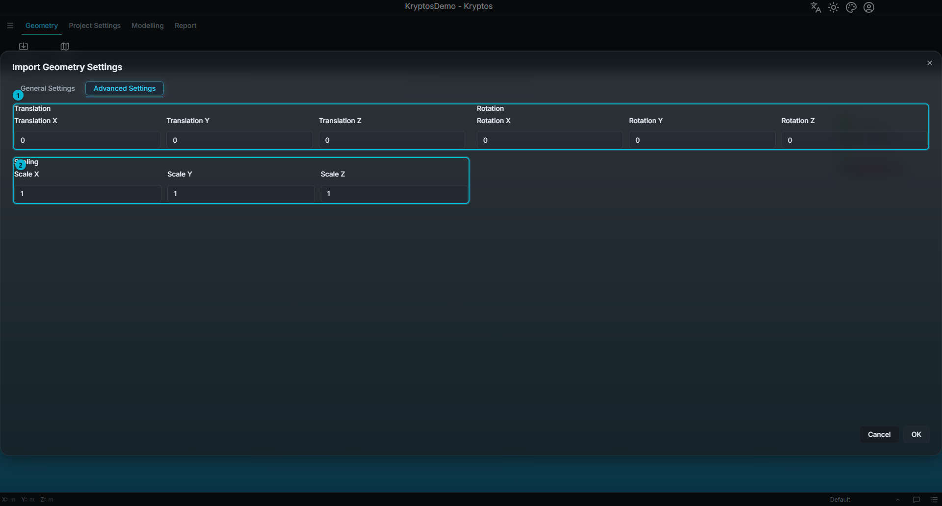
- Translation and Rotation
- Scaling
Translation, Rotation, and Scaling determine how the geometry is positioned and sized when it is imported.
All three default to no change, which imports the model according to the information contained in the source file.
Translation X / Y / Z — moves the geometry along the corresponding axis, using project units. Use these settings when a model was exported about its own origin rather than the plant origin and therefore does not align correctly with geometry already in the project.
Rotation X / Y / Z — rotates the geometry about the corresponding axis, in degrees. Each value must be between 0 and 360. Negative angles are not accepted, so enter
270instead of-90.Scale X / Y / Z — scales the model along the corresponding axis. Each value defaults to
1and cannot be negative.
WARNING
Unit conversion is applied in addition to the Scaling values, and the two are multiplied together. Use Units to specify the measurement system of the source file and Scaling only when the model itself is genuinely the wrong size.
For example, a file in feet imported into a project using metres with a Scale value of 2 is converted using both factors, resulting in an overall scale factor of 0.6096 (i.e., 0.3048 of unit conversion multiplied by scale value of 2), not just 2.
Importing a Navisworks File
When at least one of the selected files is a Navisworks file (.nwd or .nwc), the dialog shows extra options.
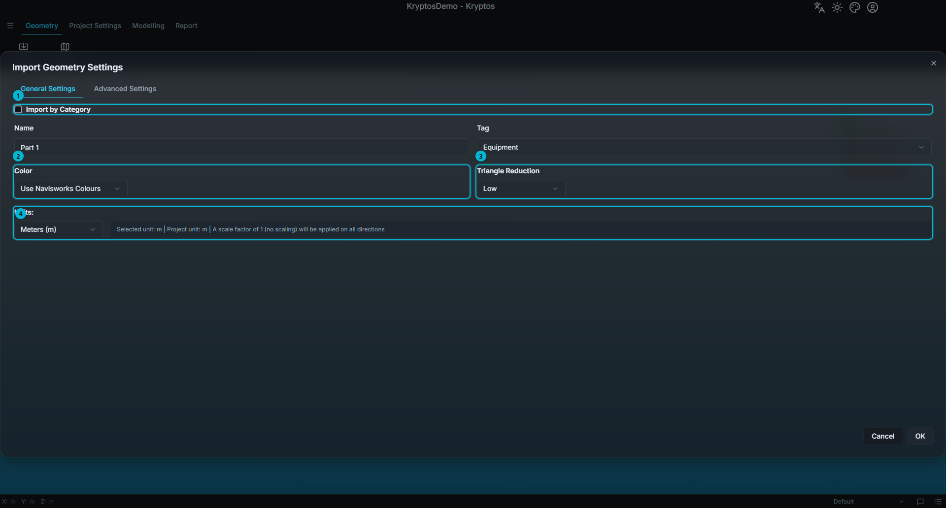
- Import by Category — splits the model into separate geometries, one for each category.
- Color — Use Navisworks Colours or Custom.
- Triangle Reduction
- Units
Import by Category
Large Navisworks models usually hold equipment, piping, structure and more in one file. Tick Import by Category to bring each of these in as its own geometry, with its own name, tag, colour and triangle reduction.
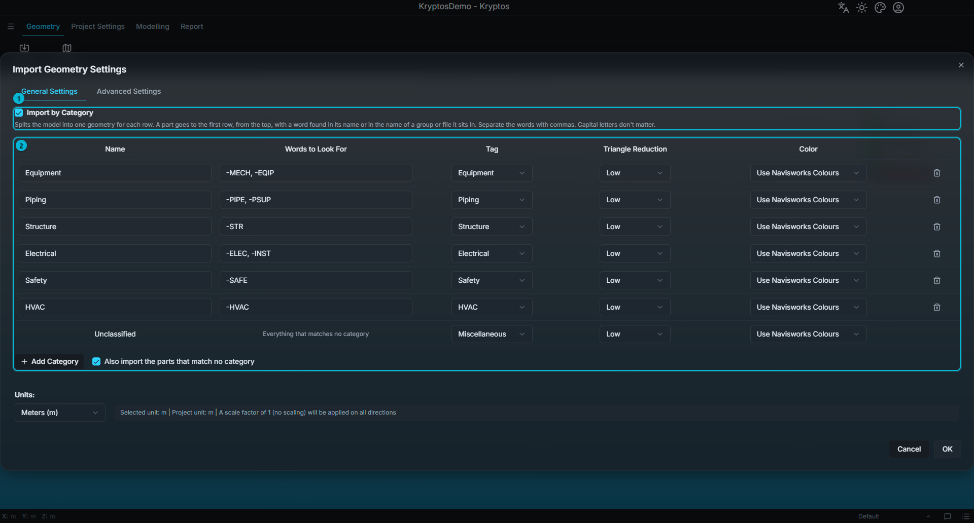
- Import by Category — switches the category table on. It replaces the single Name, Tag, Color and Triangle Reduction settings.
- Category table — one row for each geometry that will be created.
Each row has a Name, Words to Look For, a Tag, a Triangle Reduction level and a Color:
- In Words to Look For, type the words that identify this category in your model, for example
-PIPE, -PSUPfor piping. Put a comma between the words. It does not matter whether you use capital or small letters. - Kryptos checks the name of every part, and the name of the group or file the part belongs to. If a name contains one of the words, the part is placed in that category.
- Kryptos checks the rows from the top down. If a part matches more than one row, it goes to the first one.
- The rows start with a typical set: Equipment, Piping, Structure, Electrical, Safety and HVAC. Change the words to match the names used in your model, or use Add Category for more rows.
- Parts that match no row are collected in Unclassified. Tick Also import the parts that match no category to keep them, or leave it unticked to ignore them.
TIP
Model groups are often named with a dash, such as -PIPE or -STR. Starting a word with a dash also stops it from matching inside longer words. For example, -STR does not match INSTR.
Ignore Small Parts
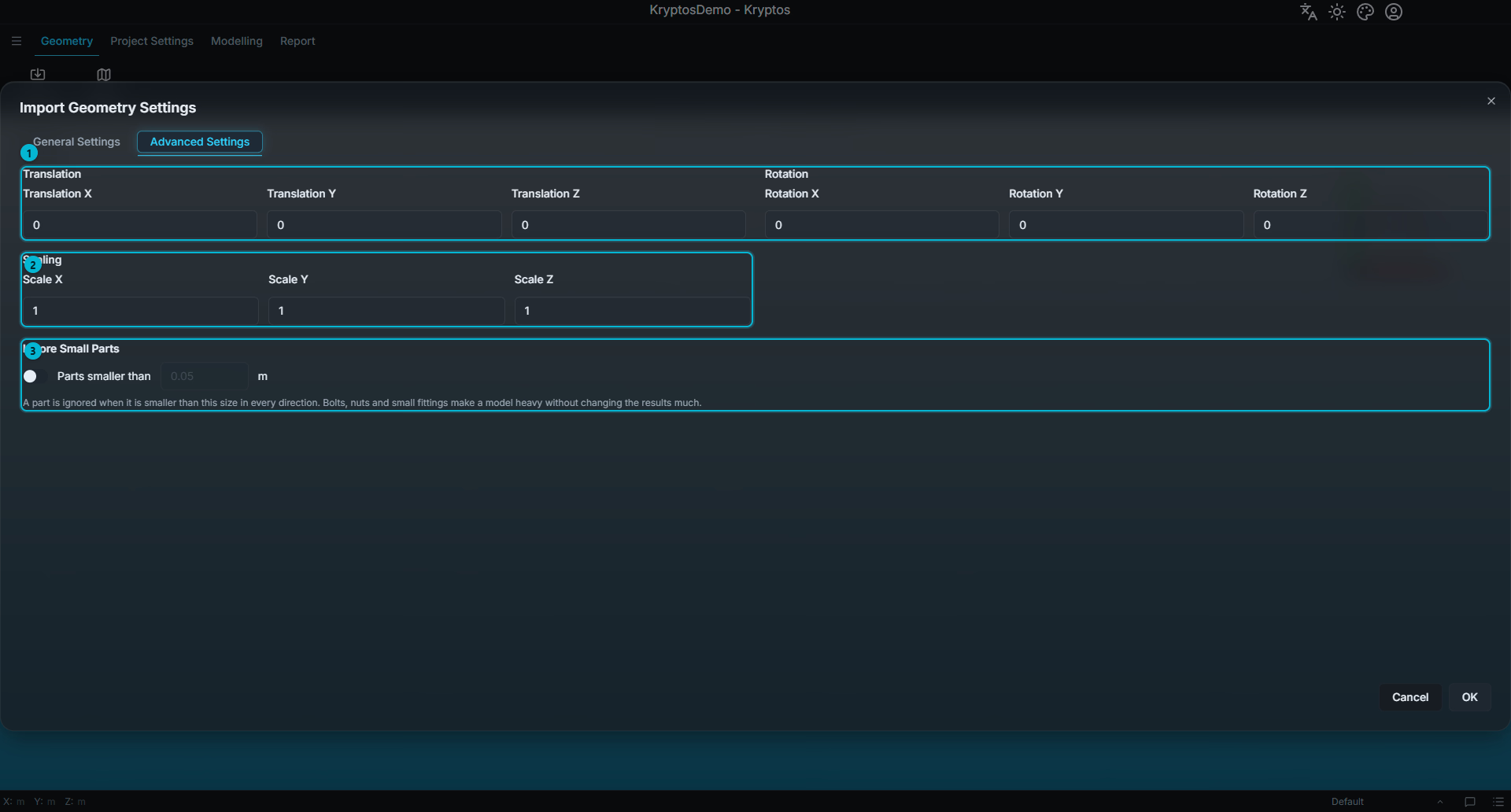
- Translation and Rotation
- Scaling
- Ignore Small Parts
Bolts, nuts and small fittings make a model heavy without changing the results much. Switch Ignore Small Parts on and enter a size. A part is ignored when it is smaller than this size in every direction. The size is in project units. The switch is off by default, so every part is imported unless you turn it on.
Edit Geometry
Once geometry has been imported, you can change how it is named and displayed without re-importing it. Edit Geometry becomes available in the ribbon when a geometry item is selected in the tree. Select the geometry part itself, for example Part 1, in the tree rather than the Geometry parent node.
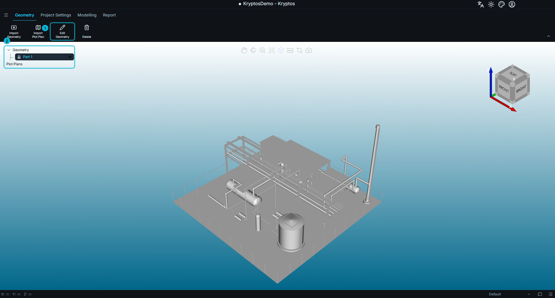
- Edit Geometry — opens the edit dialog for the selected geometry.
- Geometry tree — lists all imported geometry and plot plans. Selecting a geometry item here makes Edit Geometry available.
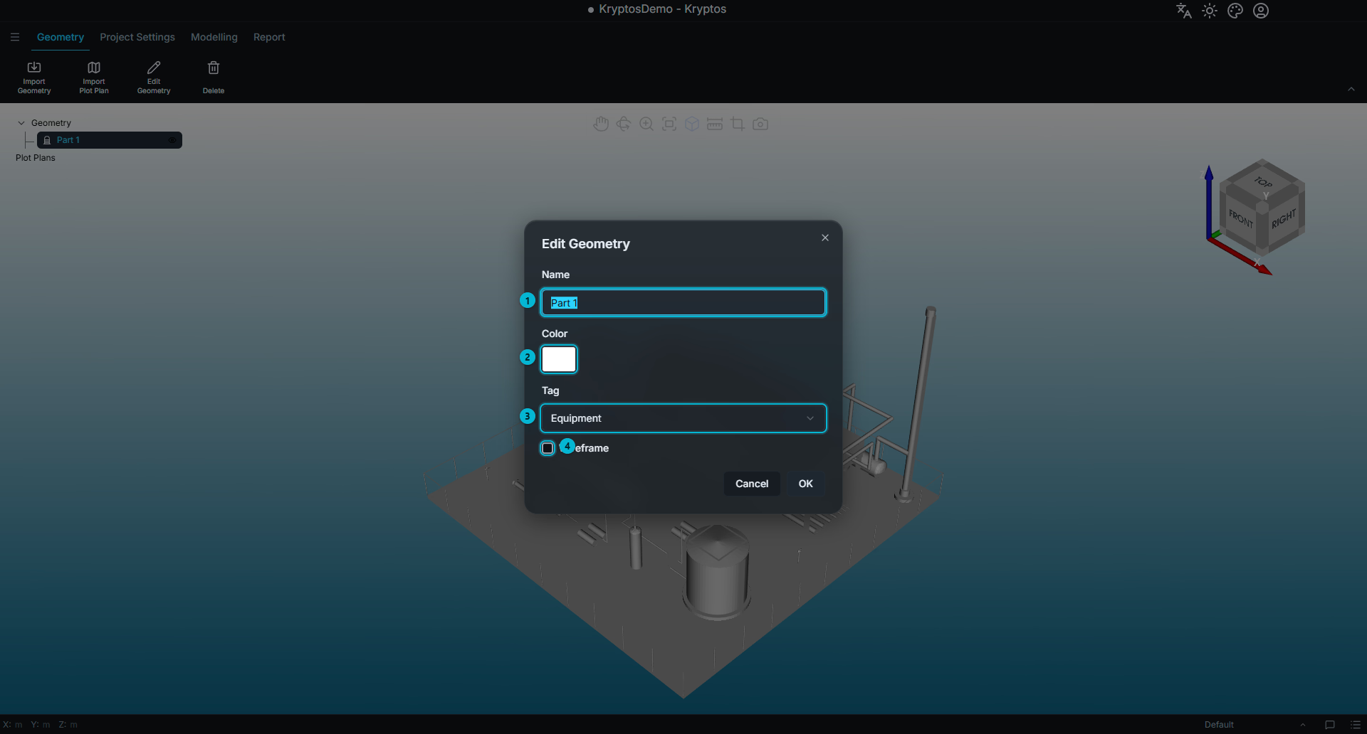
The Edit Geometry dialog contains the following options:
- Name — the name displayed in the geometry tree.
- Color — the colour used to display the geometry in the 3D viewport.
- Tag — the classification assigned during import: Equipment, Piping, Structure, Electrical, Safety, HVAC, or Miscellaneous.
- Wireframe — displays the geometry as edges rather than solid surfaces.
Wireframe affects the display only and does not modify the geometry. It can be useful for viewing objects behind a solid vessel or checking the location of imported geometry without hiding it.
TIP
You can rename any geometry part without opening the edit dialog. Select the relevant part in the tree and press F2 to rename it directly.
WARNING
The Edit Geometry dialog cannot change the placement of the geometry. Translation, rotation, scaling, and triangle reduction are applied when the geometry is imported.
If a model has been imported with the wrong position, orientation, scale, or triangle-reduction setting, you will need to delete it and import it again using the correct settings.
Import Plot Plan
A plot plan is a site drawing placed horizontally within the 3D model. It provides familiar reference points for orienting the model and positioning detectors.
Import Plot Plan is located next to Import Geometry in the ribbon.
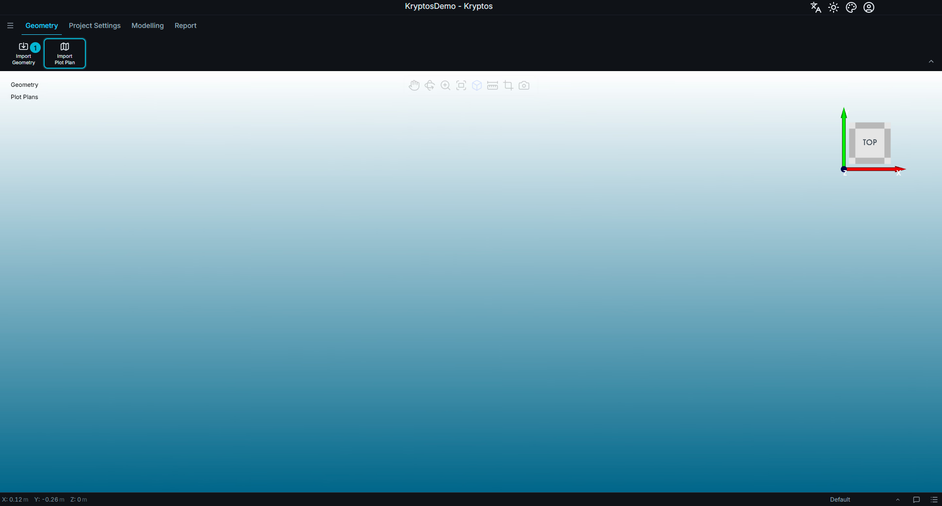
- Import Plot Plan — opens a file picker for selecting the plot plan image.
Plot plans are imported as images. Kryptos supports .png, .jpg, .jpeg and .tiff formats.
The image is placed as a separate entry under Plot Plans in the Geometry tree.
WARNING
Kryptos places plot plans flat, as top views. A side elevation or section drawing will therefore be placed horizontally, and calibration cannot be used to orient it vertically.
Use top-view plot plans only.
TIP
When a plot plan is imported, the image may initially fill the entire viewport because it is displayed at a high zoom level. Use the mouse scroll wheel to zoom out and view the plot plan in context.
Alternatively, click Reset View at the top center of the viewport to automatically fit the entire plot plan within the window. Note that this may make the plant geometry appear very small, particularly when the plot plan covers a very large area.
Plot Plan Calibration
An imported plot plan will usually not be aligned with the plant model. It may have a different rotation, position, and scale.
Select the plot plan in the geometry tree, then click Calibrate Plot Plan in the ribbon — it only appears while a plot plan is selected. This opens the calibration panel, which guides you through four stages to align the plot plan with the model. A progress bar along the top of the calibration panel indicates the current stage. Clicking Next saves the current stage and moves to the next one.
Click Calibrate Plot Plan again to hide the panel. Selecting a different item, or leaving the Geometry tab, also hides it — select the plot plan and click Calibrate Plot Plan again to bring it back.
The default view in the Calibration Panel is the Top View. This helps align the plot plan with the model easily.
1. Rotation
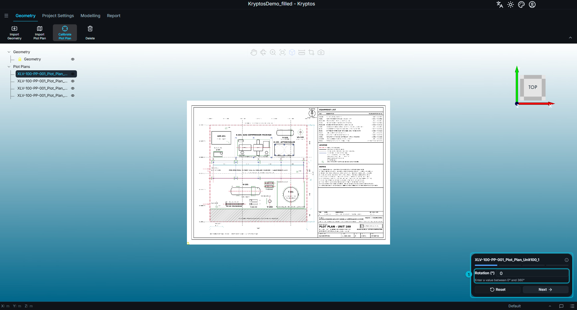
- Rotation — specifies the angle, in degrees, by which the plot plan is rotated about the vertical axis.
Enter a value between 0 and 360.
Set the orientation correctly before proceeding to the next stage. The subsequent stages position and scale the plot plan based on its current orientation.
2. Translation
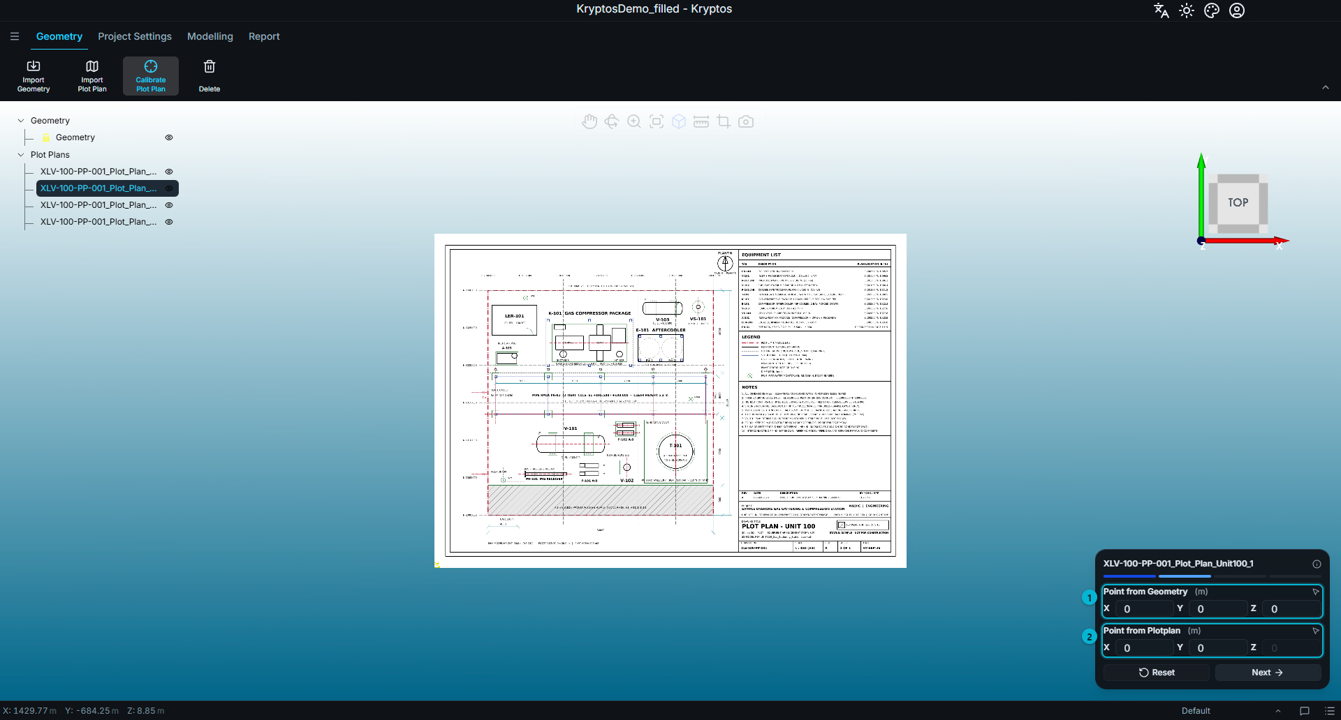
- Point from Geometry — specifies a point selected on the 3D model.
- Point from Plotplan — specifies the same physical location selected on the plot plan.
This stage positions the plot plan by matching a point on the model with the corresponding point on the drawing.
Choose a feature that can be identified unambiguously in both, such as a building corner, or column and structure intersection.
To select a point, click the arrow icon beside the corresponding row and then click the required point in the 3D workspace. Kryptos automatically fills in the coordinates. Other controls in the panel are locked while point selection is active.
TIP
If you already know the coordinates, you can enter them manually instead. The coordinate fields are editable, and point selection is provided as a convenient alternative.
3. Scaling
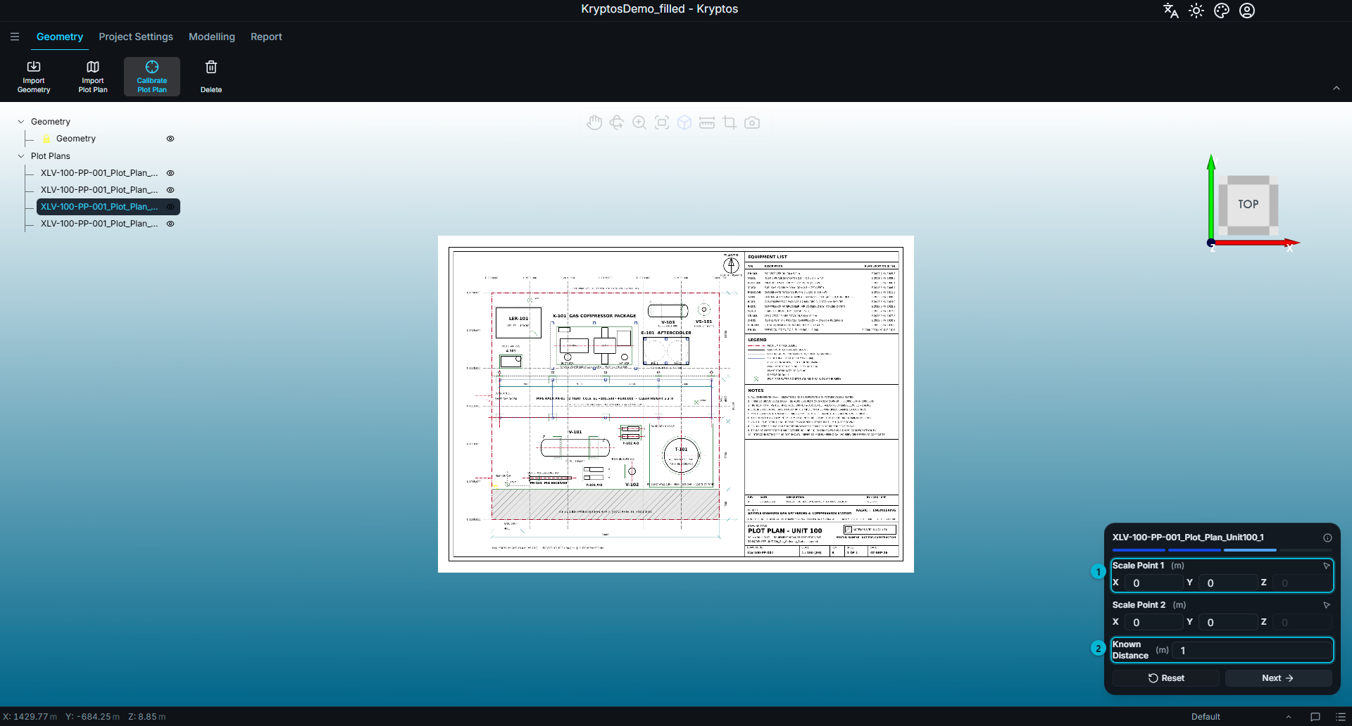
- Scale Point 1 and Scale Point 2 — two points on the plot plan whose real-world separation is known.
- Known Distance — the actual distance between those two points, specified in project units.
Kryptos compares the distance between the two selected points with the known real-world distance and scales the plot plan accordingly.
Use a dimension that is explicitly shown on the drawing, such as a grid spacing or a marked centre-to-centre distance, rather than an estimated distance.
WARNING
Known Distance must be entered in project units, not in the units used to dimension the drawing.
For example, if the project uses metres and the plot plan is dimensioned in feet, convert the distance to metres before entering it.
Where possible, select two points that are as far apart as practical on the drawing. A longer baseline reduces the effect of point-selection errors on the overall calibration.
4. Fine Tuning
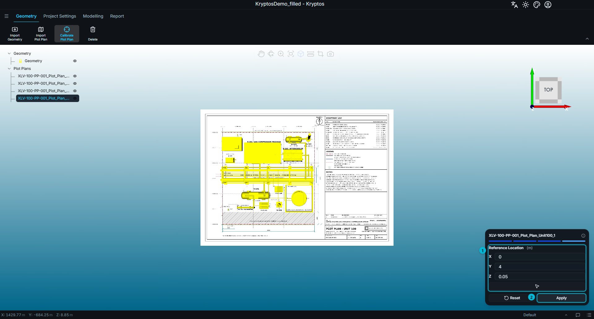
- Reference Location — provides X, Y, and Z adjustments for making final alignment corrections.
- Apply — saves the completed calibration.
At this stage, the rotation, position, and scale have already been established. Use the fine-tuning controls to make small final corrections. Adjust the values, check the result in the viewport, and click Apply when the alignment is satisfactory.
TIP
Z is particularly useful during fine-tuning. For example, suppose the ground or deck is at 5.5 m. Placing the plot plan at exactly the same elevation may cause it to overlap with the ground or deck, making the plot plan difficult to see.
In such cases, raise the plot plan slightly—for example, to 5.6 m. This small offset keeps the plot plan clearly visible, allowing you to compare equipment locations in the plot plan with those in the 3D model without the ground or deck interfering with the visualisation.
Reset clears the current calibration and returns you to the Rotation page, allowing you to start the calibration again.
Related
- Signing In & Projects — getting a project open in the first place.
- Project Settings — set the project unit before importing geometry.